When creating a cluster with the Kublr Control Plane, Kublr works with the infrastructure provider (e.g. AWS, Azure, etc) to deliver the required infrastructure (e.g. VPC, VMs, load balancers etc) and to start the Kublr Agent on the supplied virtual or physical machines.
The diagrams below show how Kublr deploys Kublr cluster in different environments: Amazon Web Services (AWS), Microsoft Azure and etc. A three master nodes and three worker nodes configuration is shown.
This diagram shows a typical AWS configuration for a Kublr cluster. It has 2 IAM Roles: one for the masters nodes and another for the worker nodes, having access to S3 bucket storing cluster secrets. All cluster resources except for the ingress or master load balancers are created inside a dedicated VPC. Worker and master nodes are launched inside auto scaling groups located in different availability zone to ensure high-availability. The worker nodes are separated from the master nodes through different security groups and routing tables. Etcd data is stored on EBS volumes created for each master.
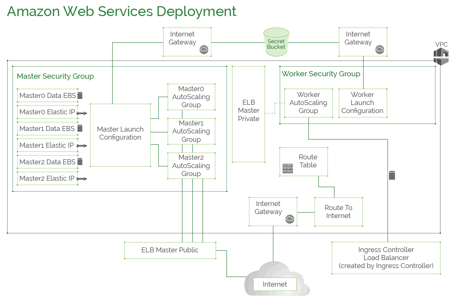
AWS deployment architecture and available configuration options are explained in more dertails in the AWS Deployment Architecture reference document.
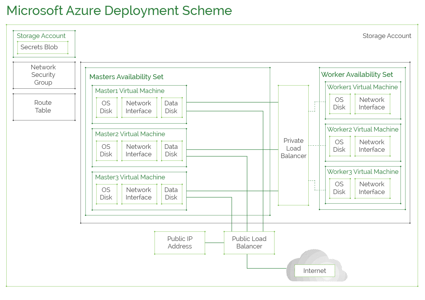
This diagram shows typical Azure configuration for a Kublr cluster. A new resource group is created for each cluster with Secrets Blob storage and virtual network for two availability sets: one for master nodes and the other for worker nodes to ensure high-availability. A public load balancer is created to balance the load between masters alongside with a private load balancer used for communciation between worker nodes and master nodes. Masters have “Data Disk” that stores etcd data.
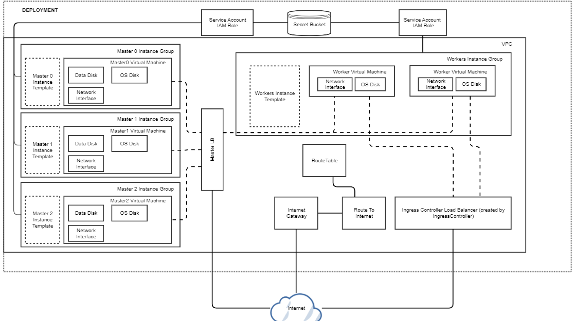
This diagram shows typical Google Cloud configuration for Kublr cluster.
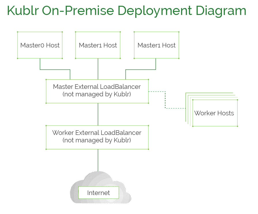
This diagram explains how on-premises Kublr clusters are deployed. Kublr requires a machine for each master and worker nodes with connectivity to each other. Additionally, two load balancers must be provisioned: one for the masters and the other for worker nodes.
This diagram shows typical vCloud Director configuration for Kublr Cluster.
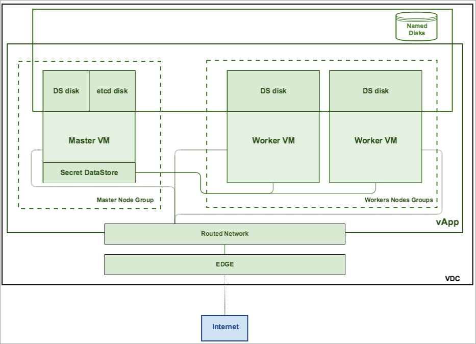
Virtual Data Center and organization should be created via the vCloud Director console. During cluster creation, VCloud organization user is used for VCLoud API and resources access. vAppTemplates should be prepared in advance and stored by means of vCloud catalog.
vApp is created for each new cluster, all VM in the vApp are connected by means of vApp network. If the cloud contains an external network, its VM can be directly connection to an Org network. If the Virtual DC contains an Edge Gateway and a network pool, vApp can be NAT-routed to an Org Network. Catalog stores vApp templates and implements a SecretStore (etcd).
The diagram below shows a typical VMware Vsphere configuration for Kublr Cluster.
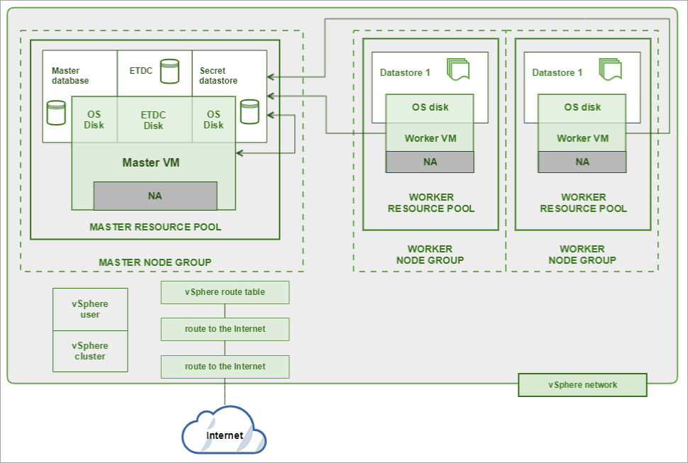
VMware infrastructure should be prepared in advance. It should include:
Resource pool control CPU and memory consumption, and spreads them among VMs. One or several resource pools can be used per each cluster. VMs of the same node group (instance group) should be deployed in the same resource pool. All master nodes should be in the same node group, worker nodes can be deployed in the several node groups. Resource pools can be nested.
Disks and OVA templates are stored in the vSphere datastore. Masters stores their OS disk in one datastore, etcd data - in another. Workers stores OS drives in the datastores too. All secrets (keys) are stored in the secret datastore. Secret datastore is used by all nodes of the cluster.
The network should be prepared in advance. Nodes can receive IP addresses from vSphere DHCP or can use static IP addresses. IP ranges should be prepared in advance, routes should be fixed. There are no special load balancers, but the existing infrastructure can be used. Terraform controllers works with vSphere API, all deployment and removing operations are executed through them. In order to use vSphere API, terraform uses special user credentials, and execute all operations in this context.